Site Navigation:
Craig's twitter feed:
Tweets by @gevmage
Every since I bought my airplane, I've wondered how the avionics switches were wired in. There are three electrical busses that are original to the aircraft, and then an avionics bus. There are two switches to turn on the avionics bus; the main one in front of the pilot, and an auxiliary one on the other side, next to the avionics breakers.
Durin gone of my checkout flights, my instructor and I were flying and wondering about debugging another problem. I had the main avionics breaker on, and we wondered about auxiliary, so we turned it on as well. A couple of seconds later, it turned off (it's a breaker-switch). We didn't know why it did that, so we left it alone. I've never touched it in the air, but I've turned it on on the ground a couple of times.
But ever since then, I've wondered how it IS wired, and why it behaved the way it did. Generally if you turn on two switches in parallel, they'll each carry less current and so be LESS likely to trip.
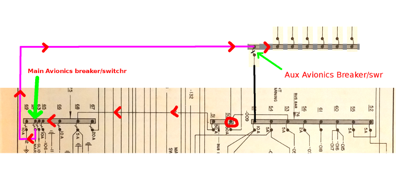
However, I think I've figured it out. Here are a series of partial electrical system diagrams. I cut out the bit of the diagram from the origianl maintenance manual for the airplane. There are three busses. The bus on the right is the "main" bus, and that feeds all the loads that are always connected. It feeds the electrical turn coordinator, and the interior lights, the lighter socket, and so on.
The bus on the left is the "auxiliary" bus, which has all the stuff that the pilot turns on and off. Landing light, navigation lights, strobes, rotating beacon, heated pitot tube, electric fuel pump and that's where my primary avionics bus switch is. The bus in the middle is called the "power" bus. It connects to the battery, to the generator, and then feeds the other two busses. In both cases below, I've circled in red the tie point where the battery and generator connect to the power bus. It's not important except that's where the current comes FROM in all cases.
One of the breaker switches on the left bus feeds the magenta (purple-ish) wire that then feeds the avionics bus up on top. The black wire on the left goes from the main bus, through a separate breaker switch (the avionics aux) and then to the avionics bus.
First, here's how current flows to the avionics bus normally. The
main avionics switch (on the left bus) is turned on, the aux avionics
switch is turned off, so the black wire on the right doesn't carry
current because it's disconnected. Current flows (marked with red
chevrons) from the power bus
through a wire to the left bus, then through the main avionics breaker
switch through the magenta wire to the avionics bus.
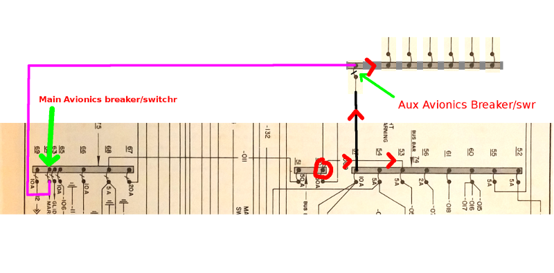
If the main avionics switch is turned off but the aux avionics switch
is turned on, here is the current flow instead. From the power bus to
the main bus up the black wire, through the aux avionics switch to the
avionics bus.
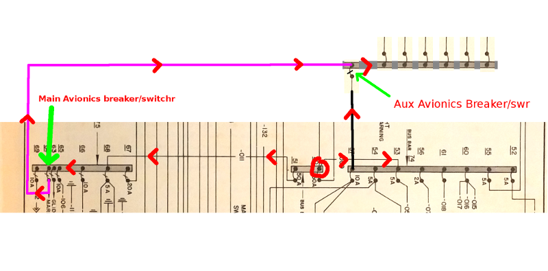
If BOTH avionics switches are turned on but there's nothing else in
the system consuming current, then the current flow looks like the
following. Some current flows through each breaker and along each
wire. Although I haven't tested it, I believe in this case that both
breaker/switches would stay turned on (wouldn't trip).
However, here it gets much more interesting. If, say, you had some
things on the left bus turned on. This would be consistent with my
circumstances when I was flying with my instructor; we were on a long
cross-country flight with some clouds, so I probably would have had
the nav lights and strobe lights on, at least. That's 10 or 12 amps
coming off the bus on the left. The current flow is something like
this:
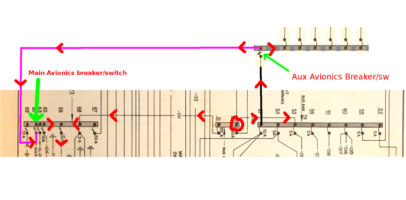
There are now TWO paths for the current to take to the left bus to
feed the lights that are on. One is the normal path from the power
bus to the aux (left) bus. However, current can also flow to the main
(right) bus, through the black wire, through the avionics aux
breaker/switch, then from the avionics bus through the magenta wire to
the aux (left) bus (opposite the normal direction of flow) and then to
the aux bus and then to the lights. How much current flows in each
branch is difficult to determine, and depends on the details of the
wires and connections, but no matter what, some current is flowing
through the aux avionics breaker switch that shouldn't be, and so its
current burden is higher than it ought to be.